https://lasma.eu/en/search/products

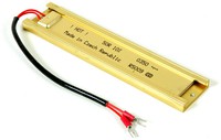
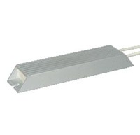
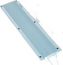
Invertek Drives Optidrive E3 has a built-in braking circuit (except frame size 1 drives), which when used together with an external braking resistor can be used to dissipate the re-generated energy from the motor that results from decelerating a high inertia load, or lowering a load against gravity. Using a braking resistor can provide faster deceleration rate when controlling high load inertia.
Where an application has high inertia, but very infrequent stops, the duty cycle of the braking resistor is low. For example, consider a motor driving a large grinding wheel via a belt drive system.
Firstly, calculate the inertia of the driven load. The grinding wheel is effectively a solid flywheel, so the inertia. J = ½ x M x r2. Where M = Mass, r = radius. So in this example, J = ½ x 500 x 0.5 x 0.5 = 62.5 Kgm2;
Secondly, convert the speeds to radians per second:
The braking energy is transferred to the motor from the driven load, so the reflected inertia at the motor shaft should be considered. Reflected inertia is calculated by dividing by the square of the drive ratio. In this case Drive Ratio = Motor Speed/Load speed= 3;
Reflected Inertia=Driven load energy/Drive ratio= 62.5 / 9 = 6.9 Kgm2;
Now, calculate the braking torque:
Braking Torque = (Total Inertia x Angular Velocity)/Required Stopping Time = (6.9 x 157.1) / 30 = 36.13 Nm
Peak Braking Power will always occur at the highest speed, so the braking power can be calculated as follows Power = Torque x Angular Velocity = 36.13 x 157.1 = 5676 Watts
This must be dissipated across the resistor from the DC Bus. Assuming a 400 Volt supply, the brake chopper operating voltages from the tables above will be as follows
Switch on Voltage = 780 Volts
The resistance required can then be determined using R = V2 / Power = (780 x 780) / 5676 = 107 Ω. It should be noted that the calculated value of the resistor is the minimum required for such an application.
It's important! For Invertek Drives Optidrive E3 series converters, a value of 1 must be set on parameter P-34 for the brake resistor.